High-frequency PCBs are a type of printed circuit board that operates at frequencies higher than 50MHz. Its physical properties can be determined by observing its traces, and these traces should be at least one third of the switching speed of the device.
When the PCB is working as a unit, the frequency of the signals generated by the circuitry is high enough to cause minimal or no effect on the circuits.
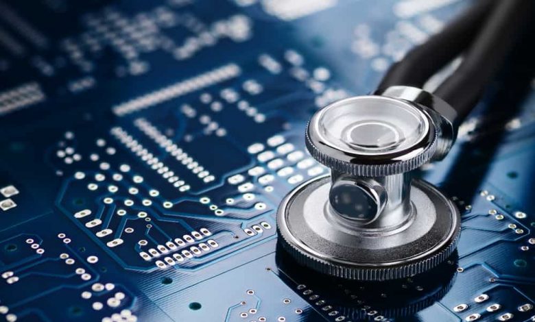
Typical uses of high-frequency PCBs include healthcare monitoring devices such as blood glucose monitors and heart rate monitors.
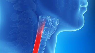
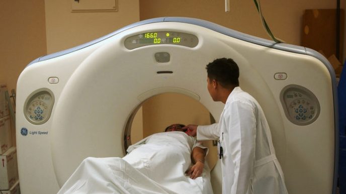
They are also used in scanning technology such as CT and MRI scanners, ultrasound machines, and X-ray machines. High-frequency PCBs are also used in scientific instruments such as microscopes and photometers. Industrial applications are another area where high-frequency PCBs are commonly used.
High-frequency PCBs are made of materials such as copper-clad laminates. These laminates are typically thicker than standard FR-4 circuit boards, and they feature special features.
These boards are usually suitable for RF designs and can be custom-made to meet any bespoke needs. They can also be manufactured using high-frequency laminates in hybrid stackups with other FR-4 laminates.
High-frequency PCBs require high-frequency generation materials to be effective. The Dielectric Constant, or Er value, varies depending on the properties of the material used. Er values range from 2.5 to 4.5. They are an important part of the design process for high-frequency PCBs. This article will discuss some of the features of high-frequency PCBs and why they are important for your device.
What is RF PCB
High-frequency PCB materials are made from various materials. The primary material used in this application is FR-4, although other materials can be used as well.
The low-loss materials include pure polytetrafluoroethylene (PTFE), ceramic-filled PTFE, and hydrocarbon ceramic.
While each material has its own properties, the overall loss factor is dependent on surface contaminants and the laminate’s hygroscopicity. Lead-free manufacturing temperatures are higher than standard soldering temperatures.
High-frequency PCBs are also different from conventional boards because they use a different design approach. The first step in high-frequency PCB design is impedance matching, with co-planar traces, vias, and ground planes.
Then, RF-compatible components must be selected, including those with higher impedance. This process is more complex than conventional PCB designs because of the EMI interference.
RF PCB and RF Circuits are complex and multi-layered affairs. The interplay between the layers allows for fine-pitch components to be assembled with ease.
Power plane layout is essential. Power plants located around the board edges can result in parasitic radiation. Decoupling components from ground planes helps to minimize capacity coupling. This is a key component of RF PCB and RF circuit design.
what are rogers pcb
What is Rogers high frequency PCB? Rogers PCB is made from materials that have a high dielectric constant and are very similar to FR4 or epoxy resin/glass woven cloth.
These materials have low water absorption, and have a lower moisture content than FR4 or epoxy resin. This is important in high frequency applications, where moisture is a significant consideration. The process used to make this material is similar to that of FR4, which are both brittle and high-frequency.
Rogers PCBs are often made with an insulating layer made of dielectric materials. Dielectric materials are those that conduct electricity poorly, which makes them good for insulating components. Dielectric materials include mica, glass, and plastics.
Metal oxides are good dielectrics. Rogers PCBs are insulated to minimize this dielectric loss, and they can be kept at o.1 mm thick and compatible with FR-4.
Unlike FR-4, Rogers PCBs are more effective and can handle high frequency applications better than FR-4. High-frequency PCBs are used for high-frequency applications, and Super PCB is proud to offer a wide range of materials for your next PCB project.
The materials used by Rogers are incredibly durable, and can withstand high temperatures and stress without degrading.
the Rogers 4350b pcb
High-frequency digital circuits are frequently made with the Rogers 4350B material. This material is a proven choice from both a functional and manufacturing standpoint.
Its complexity and yield are inversely proportional. In volume production, this difference does not matter as long as manufacturing quality and yield are important. Here are some important details about the Rogers 4350B material. Listed below are some of the advantages of this material.
The dielectric constant of Rogers 4350b PCB is 3.66. It has a stable dielectric constant in a broad frequency range and is temperature-sensitive, making it an ideal choice for high-frequency electronic projects.
Because of its dielectric constant, it is perfect for projects with high-frequency signals, such as wireless connections. Also, the materials used for this high-frequency PCB are free of PTFE, which can cause degradation and malfunction.
The dielectric constant, or Dt, plays an essential role in reducing the size of a printed circuit board. Rogers PCB material has a low Dt value, ensuring optimum functional capability in high-frequency and broadband applications. It is also suitable for low-exhaust areas.
The material is ideal for high-frequency and broadband applications, which require the lowest possible temperature. As such, it’s often more economical than ordinary PCB.
The greatest high frequency pcb manufacturer – Hemeixin Electronics Co., Limited
Hemeixin Electronics Co., Limited is one quick-turn manufacturer of prototype, various types and low volume PCBs in the world; to offer personalized one-stop solution matching the local various types and quick SMT service. Hemeixin specialize in Quick turn PCB services with an industry leading turnaround time as fast as 72 hours.
conclusion
High-frequency PCBs must be designed with controlled-impedance lines. The purpose of these lines is to prevent signal loss. Microstrip or stripline are the two most common types of high-frequency PCB. However, stripline is more advantageous than microstrip because of its ability to contain both the signal and radiation. High frequency PCBs are also referred to as HF.
The range of HF signals is between three and thirty megahertz. A high-frequency PCB is one with a frequency above 100MHz.
High-frequency PCBs require special materials to meet the requirements of high-frequency circuits. These high-frequency circuit boards require specially formulated dielectric materials, or HAGA (high-frequency printed circuit board). The loss tangent of high-frequency PCBs is caused by a change in the molecular structure of the board material. This material can be used in fast prototyping applications as well. However, it is important to specify the material used and to implement the process with the highest degree of process control.
Read more: What is SNGPC? Brief detail it Defunctions